Mobotix D12 Technical Information
Browse online or download Technical Information for Security cameras Mobotix D12. Mobotix D12 Technical information User Manual
- Page / 100
- Table of contents
- BOOKMARKS
Summary of Contents
MOBOTIX AG • Security-Vision-Systems • Made in Germanywww.mobotix.com • [email protected] • 23.11.2006Current PDF File:www.mobotix.com > Services &
1 INTRODUCTIONThe D12 camera range represents the next model of the secondgeneration of MOBOTIX network cameras. Now more powerfulthan ever, the new m
MOBOTIX AG • Security-Vision-Systems • Made in Germanywww.mobotix.com • [email protected] • 23.11.2006Current PDF File:www.mobotix.com > Services &
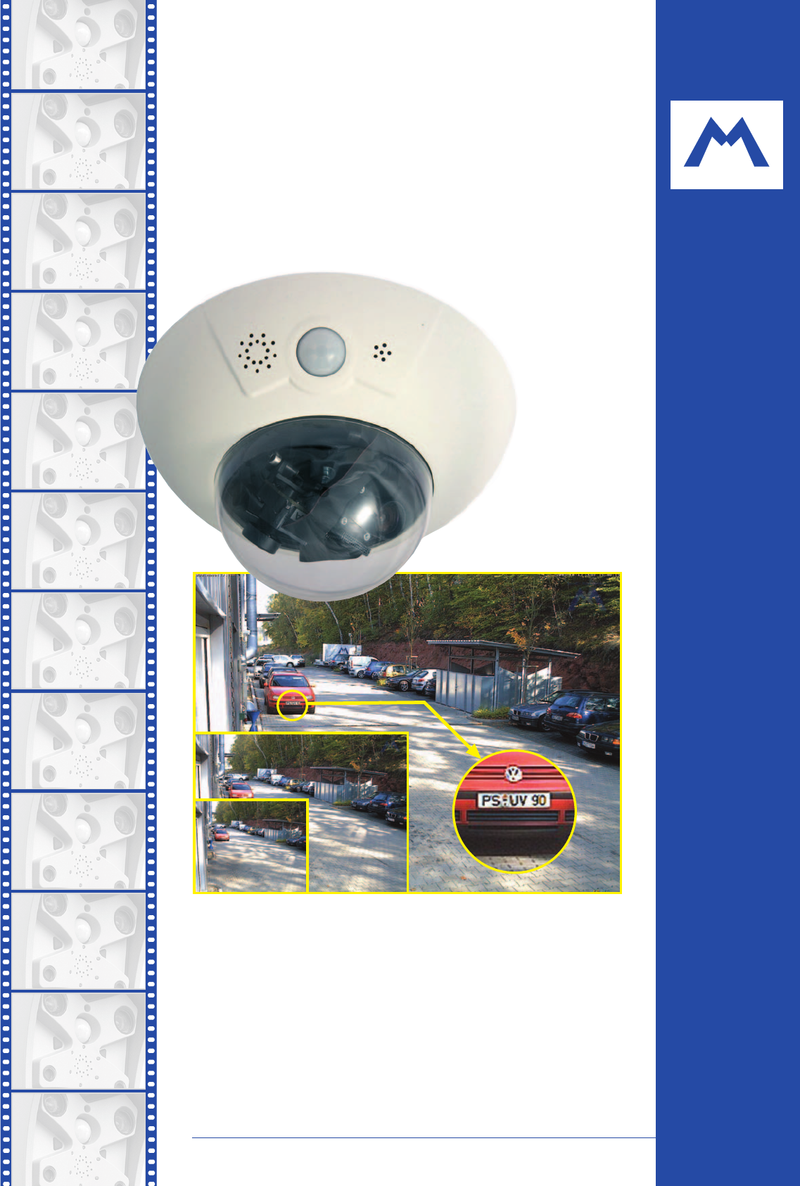
1.1 The Concept Behind the MOBOTIX D12High-Resolution Live Video (640x480) with up to 30 Frames/sThe second generation of cameras from MOBOTIX now del
images, which are not lost in the event of a power failure. If long-term storage on afile server has been set up, the SD card adds yet another layer o
Day & NightMOBOTIX Night models with two image sensors (color and B/W) deliver brilliant co-lor images during the day and crisp B/W images at nigh
Easy Installation Using the Cam-IO Installation BoxThe Cam-IO Installation box greatly facilitates setting up a security system as thismodule carries
© MOBOTIX AG • Security-Vision-Systems • Made in Germanywww.mobotix.com • [email protected] • 22.11.200613/96D12 Camera Manual Part 1Notes:
1.2 Product Advantages of the MOBOTIX D12• MOBOTIX D12 camera models support the Power-over-Ethernet standardIEEE 802.3af as well as MOBOTIX PoE techn
• Integrated data storage (ring buffer) can bridge network failures of up to4,000 images or 6 minutes video; this can be further expanded when usingan
1.3 The MOBOTIX D12D-Fixdome Outdoor1.3.1 The Concept of the MOBOTIX D12D-OutdoorAs an innovative camera system, the MOBOTIX D12D-FixDome has captured
Robust design makes for a long lifeThe outdoor wall mount is made from PBT-30GF (Polybutyleneterephtalate with30% fiberglass). This material is used h
© MOBOTIX AG • Security-Vision-Systems • Made in Germanywww.mobotix.com • [email protected] • 23.11.2006D12 Camera Manual Part 1MOBOTIX Camera
1.3.2 Product Advantages of the MOBOTIX D12D-OutdoorBesides the many product advantages inherent to the MOBOTIX D12, the MOBOTIXD12D-Outdoor offers th
1.4 Feature ListThe MOBOTIX camera includes the following main features (some features aremodel-dependent):• Live images of up to 1280x 960 pixels re
• Time Tables for handling customized days, e.g. for holidays and vacations.The time tables are used to control the camera's arming, image record
1.5 Hard- and Software Differences of the MOBOTIX D10/D12To cut a long story short – nothing changes with the basic functionality or thelooks of the
1.6 Important Notes1.6.1 Password for the Administration MenuThe administration area of the camera (Admin Menu button) is protected by a username and
1.6.4 Starting the Camera Using the Factory IP AddressIf the camera's IP address is not known any more, you can start the camera with itsfactory
1.6.8 Deactivating the Daily Reboot of the CameraIn its factory state, the MOBOTIX camera will automatically reboot every morning at3:36 am. In very r
1.6.12 Additional InformationFor more information on this topic, see the News and Functional Overview pagesin the online help of the camera's bro
2 INSTALLING THE CAMERA AND THE OUTDOOR WALL MOUNT2.1 Quick StartTo install the MOBOTIX D12D and the Outdoor wall mount follow these steps:• Checking
2.2.2 Camera Casing and Connectors of the MOBOTIX D12DThe MOBOTIX D12D-FixDome consists of three main components (camera casing(item1), body shell (i
D12 CAMERA MANUAL PART11 INTRODUCTION 81.1 The Concept behind the MOBOTIX D12 91.2 Product Advantages of the MOBOTIX D12 141.3 The MOBOTIX D12D-Fixdo
2.2.3 Delivered Parts and Components of the Outdoor Wall Mount© MOBOTIX AG • Security-Vision-Systems • Made in Germanywww.mobotix.com • sales@m
2.2.4 Dimensions of the Outdoor Wall Mount© MOBOTIX AG • Security-Vision-Systems • Made in Germanywww.mobotix.com • [email protected] • 23.11
2.3 Optional AccessoriesPower supply (MX-SNT-E/U/GB/J/AUS01-30-RJ)The MOBOTIX power supply is required if you do notuse a Network Power Box or Network
Corner and Mast Mount (MX-MH-Dome-ESWS)If you are intending to mount the camera to the cor-ner of a building or a mast, you should considerusing the M
2.4 Planning Where to Install the Camera Before installing the MOBOTIX D12D and the Outdoor wall mount (item13), thefollowing questions should be sol
2.4.3 Installation Using the Outdoor Wall MountThe lenses play a very important role when determining the correct position for thecamera. In order to
2.4.4 Deciding on the Connections (Network/ISDN/RS232)First, decide on which camera connections you would like to use.Network is keyIn general, you sh
© MOBOTIX AG • Security-Vision-Systems • Made in Germanywww.mobotix.com • [email protected] • 23.11.200635/96D12 Camera Manual Part 1ISDN oper
2.4.5 Selecting the Power SupplyIn order to reduce the amount of cabling, you should always use the Ethernet cable(NET/10BaseT) to inject power into t
2.4.6 Using Uninterruptible Power Supplies (UPS)In order to maintain a continuous power supply even when utility power fails, youshould install an uni
2.6 Preparing the Camera 412.6.1 Presetting the Lenses, Connecting the Lens Cables 412.6.2 Basic Options for Positioning the Lenses 412.6.3 Conne
2.4.7 Providing the Connections (Network/ISDN/RS232)Once the camera position, the position of the cable outlets, and the method ofpower supply have be
2.5 MOBOTIX D12 Lens OptionsMOBOTIX currently offers five different lenseswith M14 thread from Super Wide Angle(L22) with 22mm to Tele (L135) with 13
© MOBOTIX AG • Security-Vision-Systems • Made in Germanywww.mobotix.com • [email protected] • 23.11.200640/96D12 Camera Manual Part 1Focal len
2.6 Preparing the Camera2.6.1 Presetting the Lenses, Connecting the Lens CablesBefore mounting the camera to a ceiling or wall, you should preset the
2.6.3 Connecting the CAT5 CablesIf the MOBOTIX D12D-Outdoor should use a network (Ethernet) and an ISDNconnection, make sure to install a second CAT5
• Remove the rubber plug from the blue cable guide beneath the left sideof the cable cover and store the plug in a safe place.If you are only using on
• Properly lead the cable through the cableguides at the outer rim of the casing andmake sure that the outer shell can be prop-erly mounted later on.2
© MOBOTIX AG • Security-Vision-Systems • Made in Germanywww.mobotix.com • [email protected] • 23.11.200645/96D12 Camera Manual Part 1Notes:
2.7 Mounting the Casing to a Wall or Ceiling, Connecting theCables2.7.1 Drilling the Holes for the Fixtures Using the Supplied Drilling TemplateIn or
2.8 Installing the Camera with the Outdoor Wall Mount2.8.1 Setting the Direction of the Passive Infrared Sensor (PIR)When installing the camera, make
3.4.3 Simultaneously Using ISDN and Ethernet Connections (Gateway) 763.4.4 The First Image in the Browser 773.4.5 Additional Information 783.4.6 Camer
2.8.2 Installing the Outdoor Wall MountIdeally, the outdoor wall mount is mounted over the tested wall outlet, whichprovides the connections (network,
Use the supplied drilling template (at the back of this manual) to mark theposition for drilling the dowel holes and the holes through which the cable
2.8.3 Determining the Position of the Camera on the Bottom PlateOnce the outdoor wall mount has been mounted to the wall, the camera can befixed to th
2.8.4 Fixing the Camera to the Bottom PlateIn order to mount the camera to the bottom plate, use three of the supplied Allenscrews M4x25mm (item21),
• Make sure that you have properly fastened the three Allen screwsM4x25mm (item21).2.8.5 Connecting the Camera and Attaching the Bottom Plate• Plug
2.9 Completing the Installation2.9.1 Establishing a Connection to the CameraEstablish a connection to the camera as described in section 3.4, Establis
2.9.3 Attaching the Camera's Outer ShellOnce the wall mount and the camera have been assembled, it's time to attach theouter shell:• Only at
2.10 Assembling and Disassembling the Camera2.10.1 Assembling the Camera (Detailed Description)For adjusting the D12, you need the supplied Allen wren
(4) Attaching the domeTake a cotton cloth and attach the dome to the camera by turning it in aclockwise direction. This will prevent youfrom accidenta
(6) Installing the cable coverInstall the cable cover using the 3mm Allen wrench and the correspondingscrews. Take care to properly align the coverwi
SOFTWARE MANUAL PART24 CAMERA USER INTERFACE4.1 The First Image in the Browser4.2 The First Image in MxViewer4.3 Screens of the Camera4.4 The Live Sc
2.10.2 Disassembling the Camera (Detailed Description)For disassembling the outer shell of the D12, you need the supplied custom tool; fordismounting
(2) Removing the cable coverRemove the 4mm Allen screws of the cable cover and detach the cover.Note: If the cable cover cannot be detachedby hand, t
(5) Removing the cable clamps in the dome's interiorGently press the sides of the cable clamps and lift the clamps from theirseats.(6) Removing t
© MOBOTIX AG • Security-Vision-Systems • Made in Germanywww.mobotix.com • [email protected] • 23.11.200661/96D12 Camera Manual Part 1Notizen:
2.11 Cleaning Instructions2.11.1 Cleaning the Dome• In order to protect the dome from being scratched and from getting dirty,only handle the dome usin
• Avoid induction: When running data cables parallel to existing regularpower lines or high-voltage wires, make sure you observe the minimumdistances
3 OPERATING THE CAMERA3.1 General ProcedureThe MOBOTIX camera does not require any software installation; all you need isyour preferred browser with J
The configuration follows these five general steps:a) Establish the first connection (Ethernet or ISDN).b) Set the parameters for the desired connecti
3.2 Overview of the Configuration Settingss• Using the Quick Installation wizardAfter first booting the camera or after resetting it to factory defaul
Once you have finished configuring the camera, you should always storethe settings in the camera's permanent memory. You can do so in theConfigur
7.3 General Remarks on Operating the Camera7.4 Screen Display of Event Settings in Live Image7.5 Arming7.6 Events7.7 Actions and Messaging, Action and
3.3 Anschließen der Kamera3.3.1 Ethernet: Power Supply Using a Network Power Adapter (MX PoE)Make sure that you only use switches or routers that supp
2b) Connecting directly to a computer:• Connect the PC/Power connector of the Network Power Adapter to theEthernet port of the computer.• Plug the RJ4
3.3.3 Ethernet: Power Supply Using PoE Products (Power over Ethernet)• Connect the 10BaseT/NET connector of the camera to the Ethernet connectorof th
3.3.4 ISDN: Power Supply Using a Network Power Adapter(1) Push the designated connector of the ISDN split cable (MX-OPT-ISDN-SPLIT;optional accessory)
3.3.5 ISDN: Directly Supplying Power Using the External Power Supply1) Connect the ISDN connector of the camera to the S0 bus/NT.2) Plug the RJ45 conn
3.3.7 Camera Startup SequenceAs soon as the camera's power supply has been established, the six LEDs willshow the progress of the starting sequen
3.4 The First Image from the CameraAs soon as the Ethernet connection (see section 3.4.1, Preparing the Ethernet Con-nection) or the ISDN connection (
Make sure that no other network device uses the camera's IP address:• Open a command shell (Windows) or a terminal (Linux/UNIX/OSX) and enterthe
3.4.2 Preparing the ISDN ConnectionYour computer must have a properly configured ISDN card to establish a connec-tion. If your network has an ISDN rou
3.4.4 The First Image in the BrowserNow that you have successfully started thecamera for the first time, you can accessthe camera using your preferred
12 TROUBLESHOOTING12.1 Overview12.2 Troubleshooting Checklist12.3 Diagnostic Tools of the Camera12.4 Monitoring Tools of the Camera12.5 Potential Othe
3.4.5 Additional InformationFor more information on this topic, see the News and Functional Overview pagesin the online help of the camera's brow
3.4.6 Camera Screens in the BrowserPer factory default, the MOBOTIX camera first shows the Live screen. You can set adifferent start page in order to
3.4.7 The First Image in MxViewerThe MOBOTIX MxViewer is a free Windows application that allows displayingmultiple MOBOTIX cameras on one computer an
Installing and Starting MxViewerFollow these steps to install MxViewer:• Download the newest version of MxViewer:www.mobotix.com > Services > So
Automatically Searching MOBOTIX Cameras on the Same SubnetMxViewer displays the Scan network for MOBOTIX cameras dialog:• Click on the Subnetdropdown
Automatically Searching MOBOTIX Cameras on all SubnetsFuture versions of MxViewer will be able to search MOBOTIX cameras not only inthe current subnet
3.5 Starten der Kamera mit automatischer IP-Adresse (DHCP)If your network has a DHCP server, you can start the camera with DHCP support toautomaticall
3.6 Starting the Camera Using the Factory IP AddressUnder certain circumstances, resetting the camera to its factory IP address maybecome necessary. T
3.7 Connecting External Devices and Sensors: MX Interface Con-nector and MOBOTIX Cam-IO3.7.1 MX Interface Connector for Direct ConnectionsThe MOBOTIX
camera (e.g. when using a MOBOTIX camera as a video conferencing system andin access control scenarios).3.7.2 MOBOTIX Cam-IO: Expansion Module for Eas
© MOBOTIX AG • Security-Vision-Systems • Made in Germanywww.mobotix.com • [email protected] • 23.11.20067/96D12 Camera Manual Part 1Notes:
3.8 Signal Input/Output, RS232 InterfaceThe MOBOTIX camera provides a signal input/output as well as two additional sig-nal input pins and two signal
3.8.2 Signal Output PinsWhen an event is detected, the MOBOTIX camera can switch the signal output(pin1). Use the corresponding options in Setup Men
3.9 Drilling Templates D12© MOBOTIX AG • Security-Vision-Systems • Made in Germanywww.mobotix.com • [email protected] • 23.11.200690/96D12 Came
© MOBOTIX AG • Security-Vision-Systems • Made in Germanywww.mobotix.com • [email protected] • 23.11.200691/96D12 Camera Manual Part 1D12 wall
© MOBOTIX AG • Security-Vision-Systems • Made in Germanywww.mobotix.com • [email protected] • 23.11.200692/96D12 Camera Manual Part 1D12 with O
© MOBOTIX AG • Security-Vision-Systems • Made in Germanywww.mobotix.com • [email protected] • 23.11.200693/96D12 Camera Manual Part 1Basic Mod
IP65 CERTIFICATE© MOBOTIX AG • Security-Vision-Systems • Made in Germanywww.mobotix.com • [email protected] • 23.11.200694/96D12 Camera Manual
Declaration of Conformity© MOBOTIX AG • Security-Vision-Systems • Made in Germanywww.mobotix.com • [email protected] • 23.11.200695/96D12 Came
© MOBOTIX AG • Security-Vision-Systems • Made in Germanywww.mobotix.com • [email protected] • 23.11.200696/96D12 Camera Manual Part 1Notes:
All pictures in this user manual are genuine MOBOTIX camera images.Enjoy the image quality!Manufacturer: CEO:MOBOTIX AG Dr. Ralf HinkelLuxemburger St
More documents for Security cameras Mobotix D12

© 2020, manymanuals.com. All rights reserved. | 1.818 s |
 Manymanuals.com
 Manymanuals.de
 Manymanuals.fr
 Manymanuals.it
 Manymanuals.pl
 Manymanuals.cz
 Manymanuals.es
 Manymanuals-pt.com
Comments to this Manuals